See it in a video:
1. Use wire strippers to strip the ends off the black and red 6mm² solar cables. Strip the cables to approximately 7mm in length.

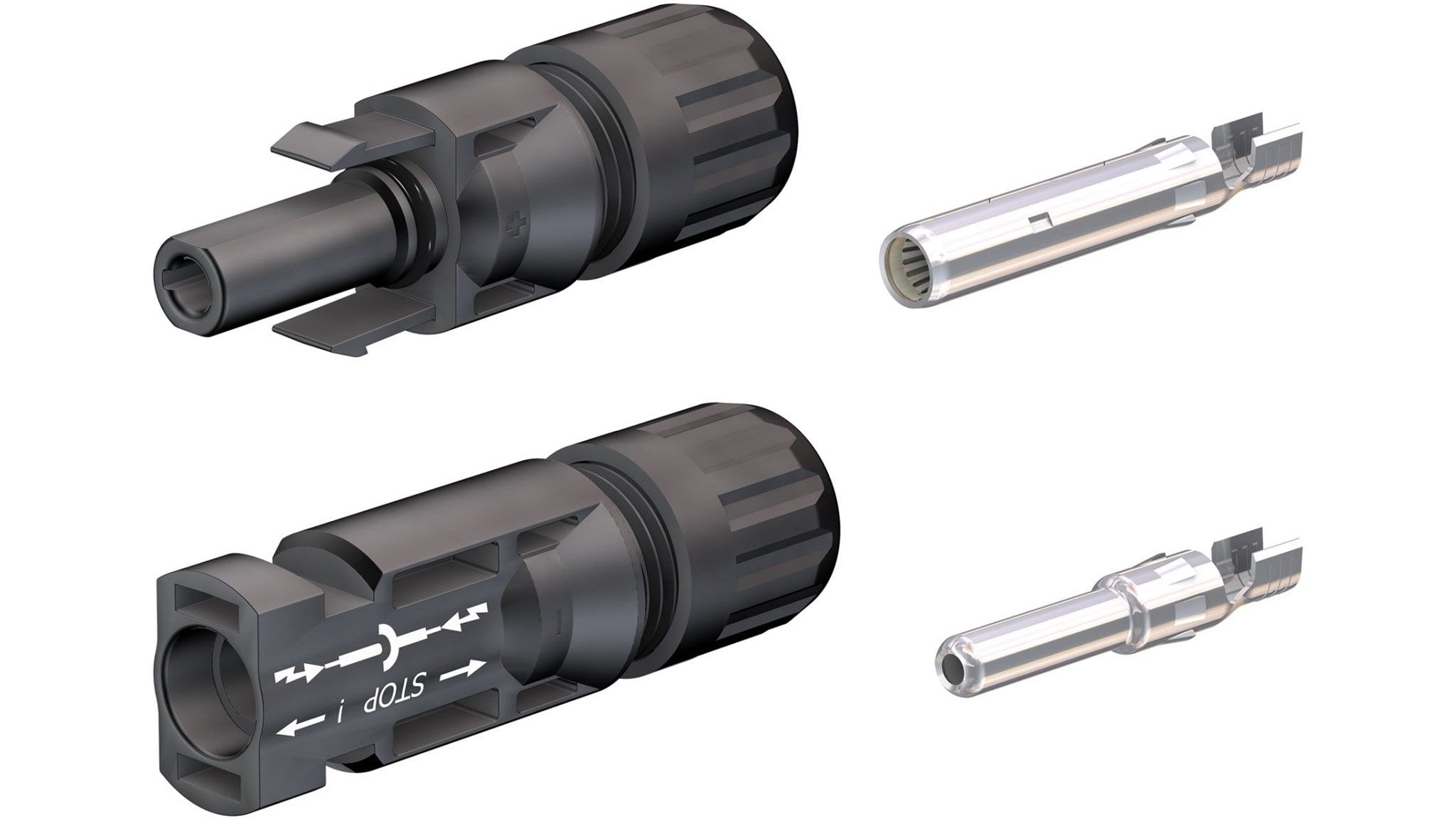
2. Ensure you use the correct metal crimp conductor, with the correct housing. Below demonstrates how each wire connects to its solar connector. The positive wire uses “Metal conductor A” (or female conductor) and “Solar connector housing A” or (male connector housing), the negative wire uses “Metal conductor B” (or male conductor) and “Solar connector housing B” (or female connector housing).

3. Starting with the red solar cable, place the silicon gland and gland nut onto the cable. Crimp “Metal Conductor A” onto the cable using the 6mm² crimping die.

4. Insert the crimped “Metal conductor A” into the “Solar connector housing A” until it clicks, then tighten the gland nut using a spanner.

5. Move onto the black solar cable. Place the silicon gland and gland nut on to the cable. Crimp “Metal conductor B” onto the cable using the 4mm² crimping die.

6. Insert the crimped “Metal conductor B” into the “Solar connector housing B” until it clicks, then tighten the gland nut using a spanner.

7. Ensure the PV Array DC isolators are in the off position. Then, connect the PV cable run from the solar panels. Ensure the other end of the cables stay disconnected from the solar panels.

8. Repeat the process of crimping MC4 connectors onto a new set of cables (refer to page 9-11), which will connect the PV Array DC isolators to the PV Array fuses.


